

Divider
Rock Bolt / Anchor (Elements) in situ Pull Out Test
(Method for Conducting Pull Out Test on Anchor Bars and Rock Bolts
IS 11309 reaffirmed 2016)
(The rock anchors are of various types and are manufactured by different agencies. The anchor pull-out test is done to get assistance in design and acceptance after installation. The types of tests and methods of testing are discussed with special emphasis on the rebar anchors, widely used in construction of tunnels, caverns and rock slope stabilisation.)
General
Rock bolts are installed as per design and specification in a rock mass for which these are designed. The rock bolts are pulled to design load to check the efficacy of the anchors installed to support the rock mass.
Also, the anchors are installed and tested in rock mass to get data for their design as related to their yield. load, ultimate capacity, and requirement of bond lengths. The pull-out test is done until the anchor or the rock fails. The results from the pull test are plotted for applied load and corresponding displacement, to assess working load and ultimate load capacity.
Summary 0f Anchor Pull-out Test Method
A rock bolt is installed in the same manner and in the same material as its intended construction use. The bolt is pulled hydraulically, and the displacement of the bolt head is measured concurrently. The bolt is pulled until the anchor system or rock fails. The ultimate and working capacities of the bolt are calculated from the plot of load versus displacement. (ASTM D 4435)
Objective of Rock Anchor Pull-Out Test
The rock bolt pull test objective is to measure
Working Capacity of rock / anchor bolt – The maximum pull test load to start pulling
Ultimate Capacity of rock / anchor bolt – the maximum pull test load at failure
To assess anchorage performance of the element by evaluating the bond strength between element and grout and between grout and rock.
To carry out investigation, suitability, and acceptance tests to assesses design parameters and their verification.
The objective of the method is to measure anchorage performance, and not the performance of the rock bolt itself.
Application of Pull-Out Test
The test is not applicable to pre tensioned element.
The test is applicable to
Mechanically anchored elements– Anchored as per given specifications.
Cement Grouted elements – The method assumes the drilled hole is of uniform size and packed with grout densely in entire length.
Resin grouted elements – Anchored as per given specifications.
(Safety and security of pull test operations are important and to be taken by the operative unit. – not discussed in this blog, however important points are considered in the checklist. Occupational Safety and Health Act (OSHA) guidelines need to be adhered.)
Important Tips on Pull-out Testing of Rock Anchors
The investigating / suitability test is done for each type of rock mass and each type of anchor. Several tests are required to be done for each type of rock mass and anchor combination. The pull test capacity gives the performance capacity, and the data can be used in design of rock bolt / rock anchor support elements.
Rock anchors are designed based on their specifications and the parameters of the rock mass in which these are to be installed. The anchors should be pretested (Proof Testing) at site to verify all design assumptions, including anchor length. Test anchors should be proof stressed to 80% of the (0.2 % strain) ultimate strength of the anchor.
Ultimate strength of the anchor is the strength at which anchor material fails in tensile test.
Temporary anchors are also tested , before installation for a proof load of 1.33 to 1.5 times the working load. (The working load is = yield load of the anchor / factor of safety: factor of safety is usually as 2.0 or as suggested by designer)
Maximum water cement ratio to be limited to 0.55 to ensure barrier against corrosion and other aggressive agents and the 28 days characteristic strength of the grout mix should not be less than 25 MPa.
The grout area should be free of vibrations and disturbance for at least 48 hours.
( A series of pull-out tests should be carried out in different representative rock mass, to prove the suitability of the rock bolts or combination of rock bolt type.
The pull-out tests shall be carried out sufficiently in advance of the installation of the rock bolts in the work area.
The detailed records of the pull-out tests, should be analysed to establish relationships between rock quality, type of rock bolts and tensioning. )
The grouted anchorage provide resistance to pull out efforts. The resistance is least of the following:
Bond resistance between the grout and rock
Bond resistance between the grout and anchor
Tensile capacity of the anchor
Important Standard Technical Definitions
SMTL – Specified Maximum Test Load (P)
Primary grout. The grout placed or injected before or after placement of tendon and prior to stressing, to secure the fixed anchor to the surrounding ground / rock.
Secondary grout – The grout injected after stressing. to bound and / or protect the free length of tandem.
Ultimate load holding capacity – (Pull out capacity)
The minimum load which causes loss of equilibrium in a part or whole of the ground anchorage.
Mechanical anchor. A mechanical device attached to the far end of a rock bolt which, when expanded against the sides of the bore hole, generates friction to provide restraint for the tensile load.
Primary reinforcement. – A term used for rock anchorages installed in underground excavations to maintain overall stability of the excavation
Secondary reinforcement. – A term used for rock anchorages installed in underground excavations to overcome localized stability problems. Secondary reinforcement may be used as the sole reinforcement or in conjunction with primary reinforcement.
Full column single speed resin type anchorage. A resin anchorage that has the bar fully bonded and is not suitable for subsequent stressing.
Two-speed resin type anchorage. A resin anchorage that utilizes fast and slow setting resin capsules that allow the bar to be stressed against the fast setting fixed anchor zone and subsequently fully bonded by the slow setting resin filling the remainder of the hole.
Rock bolt. A specific form of ground anchorage tensioned during installation, where a bar of steel or other appropriate material is fixed in rock .
Rock dowel. A specific form of un tensioned ground anchorage where a bar of steel or other appropriate material is fixed in rock.
Production anchor – anchor that forms part of the supported structure.
Prior to installation of any production anchor these anchors must be tested for proof load, for verification of anchors’ design parameters. The prof load is considered 80 percent of the anchor material yield load.
Anchor Head – the component of a ground anchor which transmits the tensile load from the tendon to bearing plate or structure.
Acceptance Test – a load test to confirm that each anchor conforms with the acceptance criteria.
Suitability Test – a load test to confirm that a particular anchor design will be adequate for the ground conditions.
Investigation test – a load test to establish the ultimate load resistance of an anchor at the grout / ground interface and to determine the characteristics of the anchor in the working load range.
Lock Off Load – the load transferred to an anchor head immediately on completion of a stressing operation.
Proof load – maximum test load to which an anchor is subjected in a particular load test.
In Situ Pull Out Test Types for Rock Anchors
Rock Anchors are subjected to various types of tests, which are done in laboratory and field.
Types and methods of grouted anchor test are given in EN ISO 22477-5
for three types of tests: (EN 1537: Execution of Special Geo- Technological Works – Ground Anchors)
Types of in situ Pull Out Tests on Rock Anchors
Only field in situ tests are discussed here. The types of tests are as follows: (Reference EN 1537 and ISRM)
S No. | EN 1537:1999 Execution of special geotechnical works – Ground anchors | ISRM | |
1 | Investigation test. | Tests before Installation of Construction Anchors | Design Tests |
2 | Suitability test. | ||
3 | Acceptance test. | Test on Construction Anchors | Proof Tests |
Test Methods for Types of Pull-out Tests.
Following tests are suggested as per EN 1537.
Displacement with Time measurements: The anchor is loaded in increments in one or more cycles up to a proof load. Displacement of the anchor head is measured over a time at the maximum load in each cycle.
Loss of Load with time measurements: The anchor is loaded incrementally in cycles from a datum load to a proof load or to failure. The loss of load at the anchor head is measured over a period at the maximum load in each cycle.
Load and Displacement Measurement: The anchor is loaded in incremental steps from a datum load to a maximum load. The displacement of the anchor head is measured under maintained load at each loading step.
Loading Pattern for Pull Out Tests for the test methods.
Loading Pattern for Pull Out Tests for all the above test methods | ||||||
Load Cycle Pattern for Performance Test / Investigating Tests /Suitability Tests / Design Tests | Load Cycle for Acceptance Test / Proof test | |||||
1 | 2 | 3 | 4 | 5 | 6 | |
AL | AL | AL | AL | AL | AL | AL |
0.25 P | 0.25 P | 0.25 P | 0.25 P | 0.25 P | 0.25 P | 0.25 P |
0.50 P | 0.50 P | 0.50 P | 0.50 P | 0.50 P | 0.50 P | |
0.75 P | 0.75 P | 0.75 P | 0.75 P | 0.75 P | ||
1.00 P | 1.00 P | 1.00 P | 1.00 P | |||
1.20 P | 1.20 P | 1.20 P | ||||
1.33 P | 1.33 P | |||||
AL= Alignment Load for removing slack from test equipment. | ||||||
All the above test methods are used for each Types of in situ Pull Out Tests on Rock Anchors. (Both temporary and permanent anchors)
Ultimate strength / Load of Anchor material = U
Design Strength / Load = U / SF = Working Load = Pw
Proof Load = (1.25 to 1.5) % of Design or Workload (Pw) = SMTL (P)
The investigation and suitability tests are specified depending on the circumstances on the project.
The tests are conducted –
By incremental loading and unloading cycles of defined load on ‘test rock bolts. The purpose is to find out the capacity of the rock bolt, the grout length. The test is conducted away from the rock mass of the structure to be supported.
The proof load (SMTL) shall be defined prior to the test and should be less than 80% of the anchor tensile strength. An example for rebars is given below.
Diameter (d) mm | Characteristic Yield Load (P) for Fe 415 Tonnes = 3.14 d2/4* 415N/mm2= | Test Load (T) = 0.8 PTonnes |
20 | 13 | 10.4 |
25 | 20.4 | 16.3 |
32 | 33.3 | 26.7 |
The acceptance test is required for onsite grouted anchors.
The anchor is subjected to tensile loading, in all type of tests and its load vs displacement is monitored and assessed against established acceptance criteria. An example for rebars is given below.
Anchor Diameter (d) | Characteristic Yield Load = (area*fy)= 3.14 d2/4* 415N/mm2 | Working Load : FS=2 | Test Load |
(1) | (2) | (3) = 0.5* (2) | (4) = 1.33*(3) |
20 | 13.0 | 6.5 | 8.7 |
25 | 20.4 | 10.2 | 13.5 |
32 | 33.3 | 16.6 | 22.2 |
40 | 52.1 | 26.1 | 34.7 |
Suggested Method Test Parameters (ISRM)-
Suggested Method Test Parameters (ISRM)- May Be Modified as Per Requirement | ||||
S No | Parameter | Design Test | Proof Test | Remark |
1 | SMTL (P) | 2 P | 1.25-1.33)*P | Parameters may be managed as per designer’s consent |
2 | AL | < 5% of SMTL | ||
3 | SMTL Loading Cycle % – P1 , P2, …… | 20 | 100 | |
4 | Loading Interval (min) | 5 | – | |
5 | Holding Time (min) | 20 | 10 | |
Design Load – Take readings in each cycle at cycle load in load rising stage. Release the load to AL, hold for 5 min and load to next cycle load. AT 100% SMTL cycle , hold the load for 20 min, and take readings. | ||||
SMTL Specified Maximum Test Load (P – to be applied in increments as P1, P2……….as percentage of SMTL)
AL | Not greater than 5 % of SMTL |
P1 | 20 % |
P2 | 40 % |
P3 | 60 % |
P4 | 80 % |
P5 | 100 % |
Indian Standard Method for Conducting Pull-out- Test
IS : 11309 – 1985 Indian Standard Method for Conducting Pull-out- Test on Anchors Bars and Rock Bots
Here the tests on Acceptance Test / Proof tests as per IS code method is described by using Load displacement method on rebars.
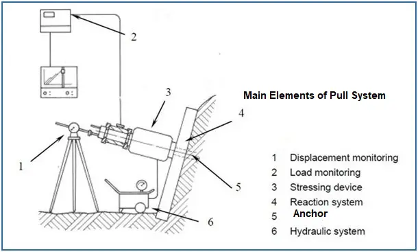
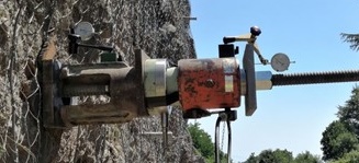
Equipment Used for Rock Bolt / Rock Anchor Pull Out Test
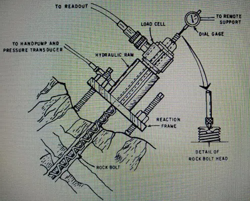
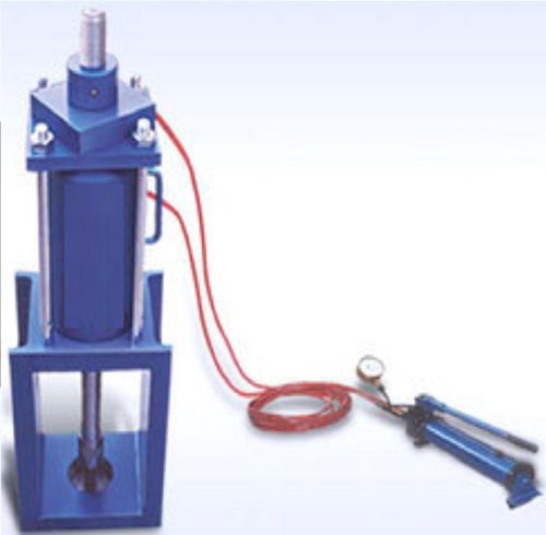
A Central hole jack with pulling system.
An electronic load cell / device to measure the load on bolt / anchor.
Displacement measurement dial gauge for 50 mm and LC of 0.025 mm.
The elements (anchor) to be tested.
Standard bearing plate, washers etc.
Drilling equipment
Torque wrench
Checklist for Rock Bolt Pull Out Test
S No | Activity – Check for | Remarks |
1 | Calibration of hydraulic jack | |
2 | Calibration of pressure gauge | Test correction must be accommodated in final readings |
3 | Calibration of displacement gauge | Test correction must be accommodated in final readings |
4 | No Compressible material at anchor head and below jack | A suitable triangular flexible stand may be used with anchor extension rod |
5 | Jack pull should be in line of anchor | |
6 | Availability of helping tools required | |
7 | Communication System | In remote or underground areas |
8 | Health hazards | Specially in underground areas |
9 | Safety requirements | PPE-in construction safety environment: Equipment operational safety |
10 | Site security requirement | Specially in remote open areas |
11 | Data collection | Displacement measurement methods may be pre decided. Scale measurements may be adopted. Two gauges may be taken for displacement measurement |
12 | Reporting requirement management | As per guidelines |
13 | Environ management checks | Pollution of air, water, land . Noise |
Procedure for Rock Bolt / Rock Anchor Pull Out Test
Test Procedure
The drill hole diameter is kept as double the diameter of the element. The standard specification follows up for hole drilling operations must be ensured.
Inspect the hole for size and length. Clean the hole with air- water jet.
Install the anchor as per manufacturer’s suggestion / technical specifications and ensure proper curing process.
After setting of the element the apparatus assembly is mounted on it as shown below.
An initial arbitrary load not greater than 5 % of SMTL shall be applied to take up slack in the equipment. (alignment load – AL)
Load Cycle for Acceptance Test / Proof test |
AL |
0.25 P |
0.50 P |
0.75 P |
1.00 P |
1.20 P |
1.33 P |
The anchor/rock belt shall be tested by increasing the load in increments until total extension greater than 40 mm is reached or bolt yields or fractures whichever is early. A suggested loading pattern is given below:
At least 3 tests shall be conducted in one rock formation. The bolts that form part of the actual rock support system shall not be tested beyond 10 percent more than the design load.
Rock-Bolt / Anchor Pull Out Test Documentation
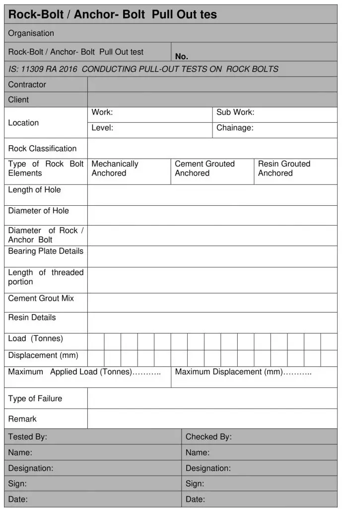
Rock Bolt Pull Out Test – load displacement curve sample -ASTM.
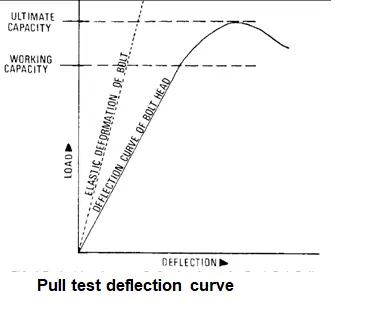
Calculation of results from the pull-out test data
The load displacement curve can be analysed for:
Working Capacity – The maximum pull test load to start pulling.
Ultimate Capacity the maximum pull test load at failure
Bond strength between Rock and Grout (Tg) can be calculated from:
Tg x 3.14 x D1 cm x L cm = W x 1000 kg
Bond strength between Rock and Steel (Ts) can be calculated from:
Ts x 3.14 x D2 cm x L cm = W x 1000 kg
Where
W = Load taken by the bar in tonnes, (Yield Load)
D1 =Diameter of rock hole in cm,
D2 = Diameter of anchor
L = Length of grout in the hole
The actual anchorage capacity of a mechanical anchorage of a rock bolt is the maximum pull exerted by the ram in tonnes.
References: Rock Bolt in situ Pull out Test
ASTM 😀 4435 – 84 (Reapproved 1998) Standard Test Method for
Rock Bolt Anchor Pull Test1
IS : 11309 – 1985 Indian Standard Method for Conducting Pull-out- Test on Anchors Bars and Rock Bots
ISRM – Commission on Testing Methods – Suggested Methods for Rock Anchor Testing
EN 1537: Execution of Special Geo- Technological Works – Ground Anchors

SK Saxena BE MBA FIE PMP (PMI) PM Consultant
Additional Links


End