
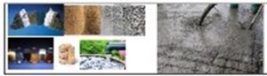
Concrete is a mix obtained when cement, sand, aggregates, and water along with admixtures are mixed. Here important checks are discussed from production of concrete to its placement. Okey Card / Inspection Request and Pour Card are also discussed.
—————————————————————————————–
Please refer to ‘different types’ of concrete at the following link:
Distinct types of Concretes
https://www.techpostsk.com/2021/09/different-types-of-concrete.html
Topics Covered
General
Types of Concrete – Nominal Mix Concrete
Types of Concrete -Design Mix Concrete
Data Required for Design Mix Concrete
Brief description for types of concrete
Summary of Different types of Concrete
Project Concrete Requirements Management
—————————————————————————————-
The following important points are briefly discussed on the blog subject.
Surface preparation of cushion concrete,
Joint Filler & adjacent face joint tie bar treatment,
Joints & Sealants Checking,
Rubber Water Stops,
Copper Water Stops,
Joint Filler Material in various thickness as per design requirement,
Bituminous Coating,
Reinforcement placement is done over the base concrete,
Material Used for Reinforcement,
Splicing / Lapping of Reinforcement,
Placing of Steel Bar,
Placement Record of Steel,
Material Used for Formwork,
Material Used for Formwork,
Surface of Formwork,
Supporting of Formwork,
Removal of Form work,
Concrete Placement Equipment,
Curing Arrangement,
- Surface preparation of cushion concrete.
(removal / chipping of defective and loose concrete & cleaning before laying the design mix concrete over base or cushion concrete.)
The base concrete is done on the raw surface, such as below the design foundation level on the prepared ground surface.

2. Joint Filler & adjacent face joint tie bar treatment
On large structures such as dams and barrages, concrete is never done in the entire length. Instead, the length of foundation area is divided into blocks of designed length. Base concrete or leveling concrete or cushion concrete in designed thickness is done for each block and over this base concrete, structural concrete RCC is done in planned height, supported by side shutters. The shutters are supported with the help of tie bars embedded in concrete. (Tie bars should not be attached to the reinforcement bars).
After the removal of shutters, the tie rods remain exposed. The concrete around these bars is removed to a certain depth as per specifications and the tie bar is cut and the hole is filled with concrete as per specifications. If not done as described, the water / moisture will corrode the bar and the process of corrosion moves further and may damage the concrete and reinforcement.
3. Joints & Sealants Checking:
The general check shall be done for the following measures / points or otherwise as per design specifications.
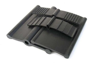
Material Used: The dimensions detailed for water stops were indicative and the specified dimensions should be followed.
(a). Rubber Water Stops. Please refer to the water stop image.
Size: 300mm wide and 8 mm thick
Lapping = 150 mm by thermal adhesion or thermal welding
Surface Cleaning
Location: Line & Elevation
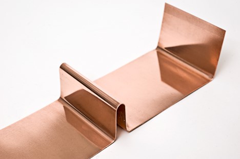
(b). Copper Water Stops
Size: 340 mm wide and 1.2 mm thick
Lapping = 20 mm by brazing and double-sided welding
Surface Cleaning
Filling of Foamed Materials
Location: Line & Elevation
4. Joint Filler Material in various thickness as per design requirement
The material used for expansion joint fillers include low viscosity epoxy resins, silicone gels, cork, and wood…. Epoxy and silicone sealants also offer excellent moisture and dirt protection.
Polyethylene Seam Fill Board is also a suitable alternative for underwater structures. Thermocol sheets used in underwater structures must be avoided as it may be harmful for aquatic animals.
- Bituminous Coating
Bitumen coat of specified grade is applied as per the following sequence:
Surface Cleaning
Surface Dry
Two layers of coating
Note: Before placing joint filler material the adjacent concrete surface must be clean, smooth, and free from form ties.
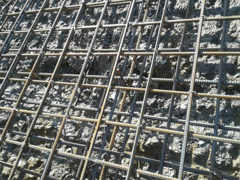
- Reinforcement placement over the base concrete.
The reinforcement must be placed over the chairs. Check for the sufficiency of these chairs.
In larger works each block may have concrete on all four sides. These blocks are separated by joints and shear keys.
Check for reinforcement provision around shear keys and joint face. Reinforcement of raft (bottom) checking as per approved drawings
Anti-crack reinforcement checking if provided.
Other Reinforcement checks:
Concrete cover (Top, Bottom & side)
Lapping of bars
Tying of bars
Spacing of reinforcement bars
Staggering of lap joints
Cleaning of bar
Steel bar coupling placement as per design
Coupler tightening
Welded Bars (weld Lap length & quality)
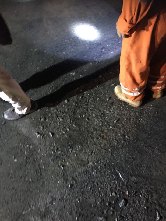
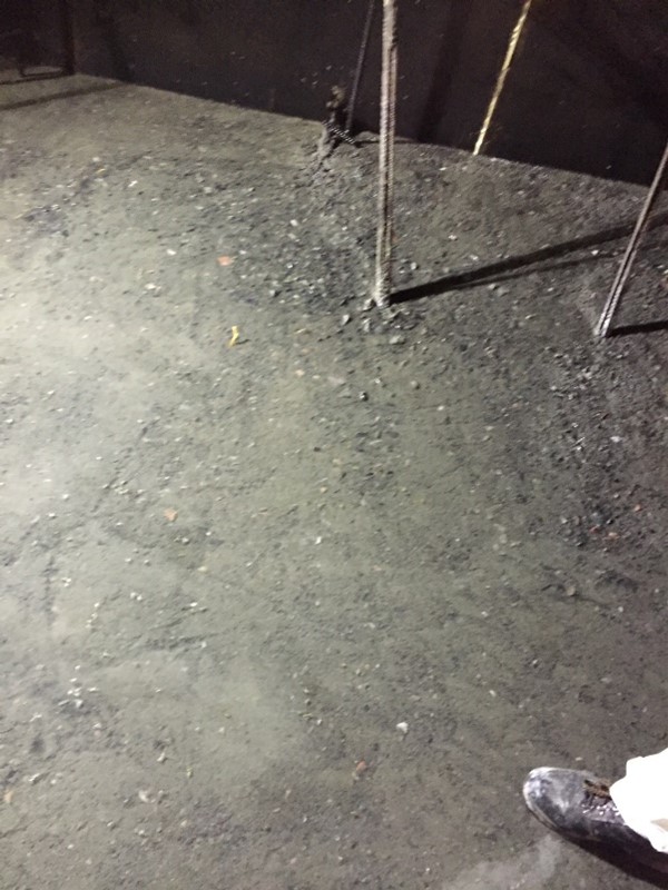
Cleaning of surface of loose material with necessary cover to reinforcement.
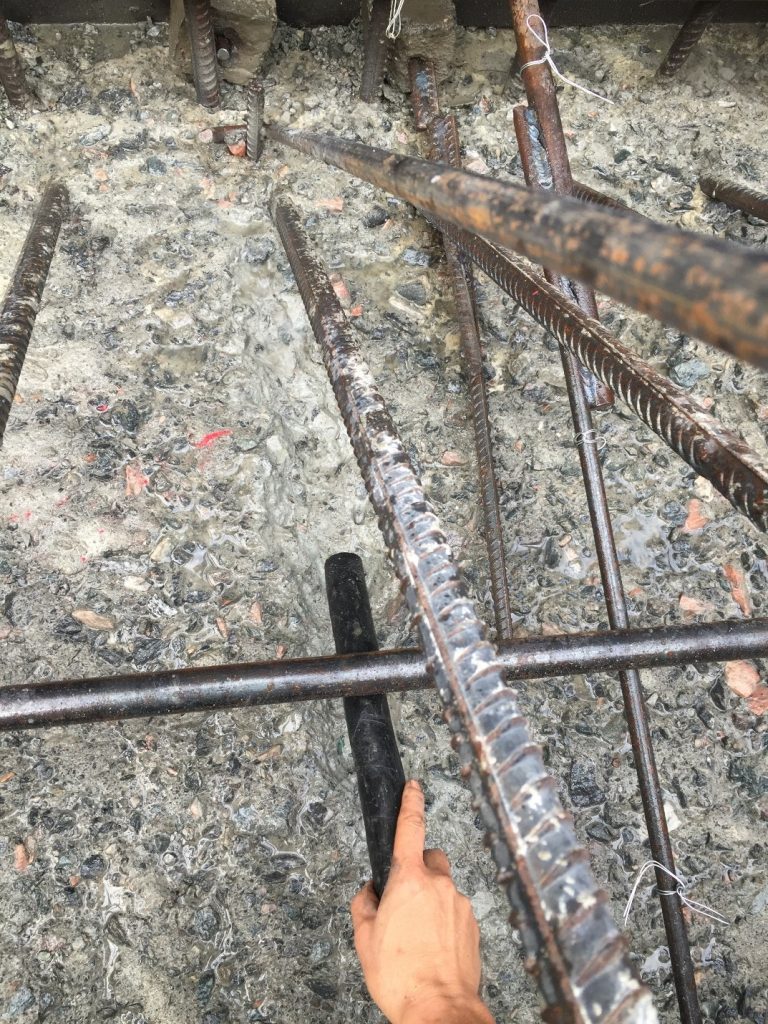
Concrete surface after green cutting and cleaning
Material Used for Reinforcement
Grade of steel
Free from loose mill scale, rust, grease, paint, splashed concrete or other coatings
Splicing / Lapping of Reinforcement
Overlap Length
Welding: Single weld / double weld length
Coupler Tightening
Stagger of lapping
Line
Required Elevation
Diameter
Length
Shape
Number
Spacing
Plumb for Vertical Bars
Cover – Side, Top & Bottom cover
Concrete Cover Block
Sufficient steel chairs, spacers, hangers, and any other steel supports
Tying of steel bar with binding wire, diameter of binding
wire > 1.6 mm
Placement Record of Steel
Bar Mark
Diameter of bar
Number
Sizes
Length
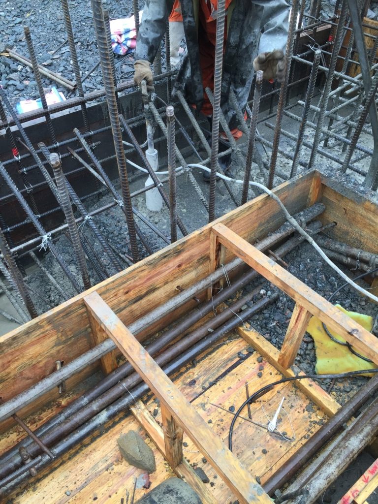
7 Form Work
Form work must be checked for the following:
Weight
Straight / smooth (Free from depression)
Cleaning
Oiling
Line and layout
Required markings for concrete levels
Plumb / Verticality / inclined angle of forms
Hole / Gap filling / taping
Tie bar / Anchor bolt (must not be welded or tied with main reinforcement)
Plywood
Steel
Timber
Any other
Straight / smooth (Free from depression)
Cleaning
Oiling
Formwork Support
Ties
Anchor Bolt
Props
Others
Hole / Gap Sealing of Formwork
Mastic tape
POP
Mortar
Any other
Removal of Form work
Lifts 1.5m and under – Not less than 24 hours
Lifts over 1.5m – Not less than 48 hours
Tunnel Linings – Not less than 16 hours
Mass Concrete – Not less than 24 hours
After the removal of shutters, the tie rods remain exposed. The concrete around these bars is removed to a certain depth as per specifications and the tie bar is cut and the hole is filled with concrete as per specifications. If not done as described, the water / moisture will corrode the bar and the process of corrosion moves further and may damage the concrete and reinforcement.
As such all the tie bars on the face are treated and the entire side surface is covered to maintain a joint between the blocks. The surface may be painted and provided with a spacer sheet of designed thickness. This is done to maintain the separation between the blocks.
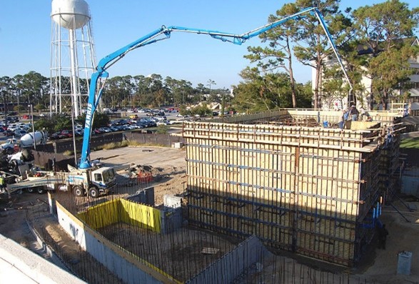
8. Concrete Placement Equipment
Tower Crane
Other Cranes
Concrete Dumping
Conveyor Belt – Function ability of conveyor belt, drop height of concrete
Pumped Concrete
Concrete Placer
Onsite mixers and Batching Plants
Transportation of Concrete
Ready Mix Concrete
Understanding Ready Mix Concrete RMC Framework
Concrete placement plan Requirements
Transit Mixers – Number
Rear Dumpers- for small reach of concrete placement
Pumped Concrete – It is high slump concrete where aggregates remain in suspension in concrete mass during pumping operation. Poor slump control may lead to segregation of aggregates which may lead to chocking of supply pipe system.
Concrete Placer Pump – It can place the concrete at desired coordinate in open area concrete placement concrete.
Thermal insulation to concrete – to manage temperature variations (to manage temperature difference in manufactured concrete and placed concrete )
Vibrator Numbers required including emergency requirement
No movement of concrete by vibrators by vibrator
9. NSPECTION CHECKLIST – CONCRETE PLACEMENT
The following aspects of concrete placement should be reviewed:
Placing area is clean and free of loose concrete, mud, and other debris that could jeopardize the quality of the structure.
Reinforcing steel and embeds are clean and free of loose rust, grease or other matter that may adversely affect concrete bond.
Reinforcement and embedded parts are as per drawing.
Joints and surfaces to receive concrete are free of deleterious materials and well formed.
Forms are clean, free of foreign materials and oiled.
Concrete is placed in a manner to prevent segregation.
Placement of concrete is made in lift thickness as specified and within time restrictions between lifts for high lift placements.
Concrete is properly vibrated.
Placement is made to avoid excessive drying of fresh concrete before next lift is placed.
Concrete is sampled and tested at specified frequency for strength, slump, temperature and unit weight.
Concrete is brought to final grade and finish.
The surface is protected by covers and cured properly. Curing arrangements must be sufficing the requirement.
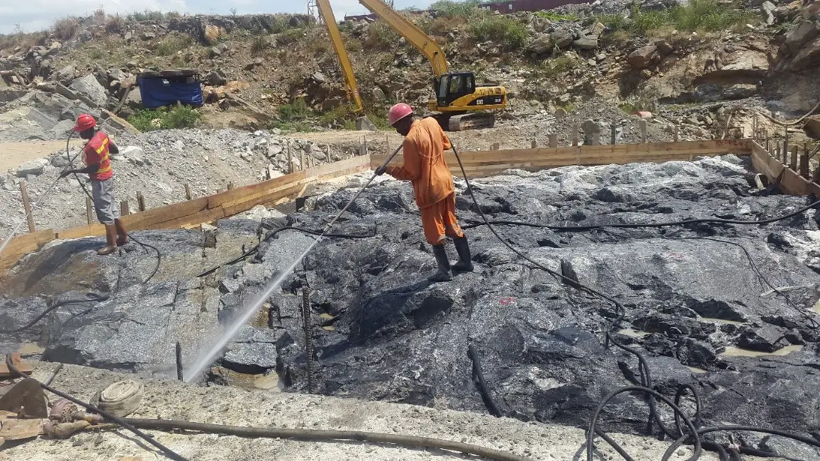
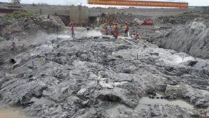
Green cut the concrete surface to remove mortar to expose the aggregates and loose concrete if any and cleaning of rebars
Inspection of the surface to be done after form removal and the surface shall be jointly inspected before any repairs.
Check for availability of concrete ingredients at batching plant, staff for operation, transportation facilities and testing facilities at plant.
Follow the Inspection Request check sheet closely for final approval.
All the work shall conform to the technical specifications.
Anything abnormal during the concrete process cycle shall be reported to Construction Agency immediately.
9. INSPECTION CHECKLIST – CONCRETE PLACEMENT
The following aspects of concrete placement should be reviewed:
- Placing area is clean and free of loose concrete, mud, and other debris that could jeopardize the quality of the structure.
- Reinforcing steel and embeds are clean and free of loose rust, grease or other matter that may adversely affect concrete bond.
- Reinforcement and embedded parts are as per drawing.
- Joints and surfaces to receive concrete are free of deleterious materials and well formed.
- Forms are clean, free of foreign materials and oiled.
- Concrete is placed in a manner to prevent segregation.
- Placement of concrete is made in lift thickness as specified and within time restrictions between lifts for high lift placements.
- Concrete is properly vibrated.
- Placement is made to avoid excessive drying of fresh concrete before next lift is placed.
- Concrete is sampled and tested at specified frequency for strength, slump, temperature and unit weight.
- Concrete is brought to final grade and finish.
- The surface is protected by covers and cured properly. Curing arrangements must be sufficing the requirement.
- Green cut the concrete surface to remove mortar to expose the aggregates and loose concrete if any and cleaning of rebars
- Inspection of the surface to be done after form removal and the surface shall be jointly inspected before any repairs.
- Check for availability of concrete ingredients at batching plant, staff for operation, transportation facilities and testing facilities at plant.
- Follow the Inspection Request check sheet closely for final approval.
- All the work shall conform to the technical specifications.
- Anything abnormal during the concrete process cycle shall be reported to Construction Agency immediately.
10. Curing Arrangement
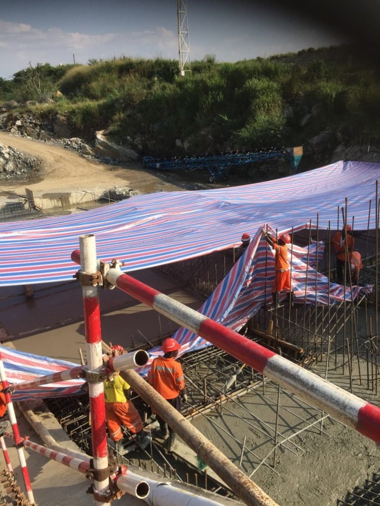
Check arrangements for curing such as for clod weather curing and hot weather curing
Embedding concrete temperature measurement device –
Location & numbers
Frequency of temperature measurement decision.Inlet & outlet of pipe design, layout, location in case curing is facilitate by embedded hot water pipes.
Time and method for green cutting and arrangement- After 8-10 hours completion of concrete with air-water jet
Arrangement for shading of concrete pour
Reinforcement and Embodiment summary sheet.
All above points must be kept in mind before going for supervision checks. The checks suggested are of generic nature. These checks must e modified in reference to drawings, specification, and approved methodology. Constructing agency must ensures that all the check points are taken care before asking the supervision agency for inspection and getting Okey of the work.
Accordingly, Inspection requests or okey cards format are prepared as per requirement and should be submitted for getting approval. A samples format is given below.
Inspection Request Format or Okey card Format